
Duct Sizing Chart and Method: Velocity, Friction Loss and SMACNA Construction Classes
A duct sizing chart relates airflow, duct diameter, air velocity and friction loss so that ducts can be sized to a chosen friction rate without exceeding noise-related velocity limits. At a common design friction rate of 1 Pa/m (about 0.12 in.wg per 100 ft), a galvanized round duct carrying 1,000 L/s (about 2,120 cfm) works out to roughly 440 mm diameter at about 6.5 m/s. The final design must use the project's own calculation, fitting losses and the SMACNA construction class that matches the system pressure.
- How to read a duct sizing chart
- Duct sizing chart: round galvanized duct at 1 Pa/m
- Velocity limits for main and branch ducts
- Equal friction vs static regain
- Equivalent length of duct fittings
- Fan static pressure calculation: worked example
- SMACNA duct construction standards
- Ductwork fabrication and installation in Saudi Arabia
How to read a duct sizing chart
A duct sizing chart is the quickest way to turn an airflow into a duct size. The duct sizing chart plots airflow against friction loss per meter for a given duct material and air density, with lines for each diameter and each air velocity, so one reading gives the size, the velocity and the pressure lost. The best-known duct sizing chart is the ASHRAE friction chart for round galvanized steel, which is built on the Darcy-Weisbach equation and the Colebrook friction factor (Air Conditioning Lounge). The chart below is an original duct sizing chart calculated from the same physics, for standard air at 1.2 kg/m³ and a duct roughness of 0.09 mm, the same basis as the SI friction chart in the ASHRAE Handbook.
Reading a duct sizing chart takes three steps: find the airflow on the horizontal axis, move up to the design friction rate, and read the nearest diameter line and velocity line at that point. That first reading is only the starting size. Friction rate, velocity limits, fitting losses, fan static pressure and construction class all interact, and long duct runs, high cooling airflows and ceiling voids crowded with services make those interactions more severe. This guide works through each step and links it to SMACNA construction requirements and to ductwork fabrication and installation in Saudi Arabia. For project delivery, see White Arch HVAC services.

Duct sizing chart: round galvanized duct at 1 Pa/m
The values below were calculated with the Darcy-Weisbach equation and the Colebrook friction factor for galvanized steel (absolute roughness 0.09 mm) and standard air (density 1.2 kg/m³). Diameters are the calculated values; select the next larger size available from the fabricator. Values are approximate, and design must use the project's own calculation.
| Airflow (L/s) | Airflow (cfm) | Round duct diameter (mm) | Diameter (in) | Velocity (m/s) | Velocity (fpm) |
|---|---|---|---|---|---|
| 50 | 106 | 145 | 5.7 | 3.1 | 605 |
| 100 | 212 | 185 | 7.3 | 3.7 | 725 |
| 150 | 318 | 215 | 8.5 | 4.1 | 805 |
| 200 | 424 | 240 | 9.5 | 4.4 | 865 |
| 300 | 636 | 280 | 11.1 | 4.9 | 955 |
| 400 | 848 | 315 | 12.3 | 5.2 | 1,025 |
| 500 | 1,059 | 340 | 13.4 | 5.5 | 1,085 |
| 750 | 1,589 | 395 | 15.6 | 6.1 | 1,200 |
| 1,000 | 2,119 | 440 | 17.4 | 6.5 | 1,285 |
| 1,500 | 3,178 | 515 | 20.2 | 7.2 | 1,420 |
| 2,000 | 4,238 | 575 | 22.6 | 7.7 | 1,525 |
| 3,000 | 6,357 | 670 | 26.3 | 8.5 | 1,680 |
| 4,000 | 8,476 | 745 | 29.4 | 9.2 | 1,805 |
| 5,000 | 10,594 | 810 | 32.0 | 9.7 | 1,905 |
Two points stand out. First, 1 Pa/m is slightly higher than the 0.08 to 0.10 in.wg per 100 ft (about 0.65 to 0.8 Pa/m) often used in IP practice, so ducts sized to those lower rates will be somewhat larger. Second, above roughly 2,000 L/s the velocity at 1 Pa/m passes 8 m/s, which may be too high for mains above occupied spaces; there, the velocity limit governs and the duct should be upsized.
For rectangular ducts, the equivalent round diameter for equal friction and airflow is De = 1.30 × (a × b)^0.625 / (a + b)^0.25. This is the Huebscher equation, from R.G. Huebscher's 1948 research on flow resistance in ducts of different shapes, and it is the basis of the slide-rule duct calculators still used on site (SNIPS). A 600 × 300 mm duct, for example, is equivalent to a round duct of about 457 mm. Note that the equivalent round duct has a smaller cross-sectional area than the rectangle, because corners add friction. Keep aspect ratios moderate, ideally no more than about 4:1, to limit friction, material and noise.
| Rectangular duct (mm) | Equivalent round diameter (mm) |
|---|---|
| 400 × 200 | 305 |
| 600 × 300 | 457 |
| 800 × 400 | 609 |
| 1,000 × 500 | 762 |
| 1,200 × 400 | 731 |
Velocity limits for main and branch ducts
Friction rate alone does not control noise. Typical velocity ranges for low-pressure commercial comfort systems are shown below; they are indicative, and the acoustic target (NC or RC rating) for each space and the duct location should decide the final value. A duct sizing chart shows velocity alongside diameter so both checks can be made from one reading.
| Duct section | Indicative velocity (m/s) | Indicative velocity (fpm) |
|---|---|---|
| Main supply ducts in shafts or plant areas | 8 to 10 | 1,600 to 2,000 |
| Main supply ducts above occupied ceilings | 5 to 8 | 1,000 to 1,600 |
| Branch ducts | 3 to 5 | 600 to 1,000 |
| Final runouts to diffusers | 2 to 3.5 | 400 to 700 |
| Return and exhaust mains | 4 to 6 | 800 to 1,200 |
Noise-sensitive spaces such as hospital wards, auditoriums, studios and executive offices need the lower end of each range, while plant rooms and service corridors tolerate higher values. Velocity also sets velocity pressure: for standard air, Pv (Pa) = 0.6 × V², so 5 m/s gives 15 Pa while 10 m/s gives 60 Pa. Doubling velocity quadruples the pressure every fitting works against, which is why high-velocity mains need careful fitting selection.
Also read: Cooling Load Calculation for Buildings in Saudi Arabia: Design Conditions and Method
Equal friction vs static regain
The two main duct sizing methods produce different layouts and different balancing effort.
| Aspect | Equal friction | Static regain |
|---|---|---|
| Principle | Every section is sized for the same friction loss per meter | Each section is sized so the static pressure regained from a velocity reduction offsets the loss to the next outlet |
| Best suited to | Low-pressure supply, return and exhaust systems | Long supply mains with many takeoffs, VAV systems, higher-velocity mains |
| Result | Simple, fast and widely used; pressure at outlets varies along the run | More uniform static pressure at takeoffs, less balancing, sometimes larger downstream ducts |
| Effort | Hand calculation or a duct sizing chart | Iterative; usually done in duct design software |
Many projects use equal friction for returns and short systems and static regain or a software-optimized approach (such as the T-method) for long supply mains. Equal friction is the method a duct sizing chart supports directly, since each section is read off the same friction line. Airflow for each section comes from the load calculation; our BTU to ton conversion guide covers the capacity side.
Equivalent length of duct fittings
Elbows, tees, transitions and dampers create dynamic losses. The loss through a fitting is Δp = C × Pv, where C is the loss coefficient and Pv is the velocity pressure; for standard air, Pv (Pa) = 0.6 × V², with V in m/s. The equivalent length of duct fittings expresses the same loss as a length of straight duct: Le = C × D / f, where D is the diameter and f the Darcy friction factor.
For the 440 to 450 mm duct carrying 1,000 L/s at about 6.3 m/s (Pv of about 24 Pa, f of about 0.017), indicative values for the equivalent length of duct fittings are:
| Fitting (indicative C) | Loss (Pa) | Equivalent length |
|---|---|---|
| 90° smooth-radius round elbow, r/D = 1.5 (C about 0.15) | About 3.6 | About 9 diameters, roughly 4 m |
| 90° five-gore round elbow, r/D = 1.5 (C about 0.25) | About 6 | About 15 diameters, roughly 6.5 m |
| 90° mitered round elbow without vanes (C about 1.2) | About 28 | About 70 diameters, roughly 31 m |
The mitered elbow alone costs as much pressure as 30 m of straight duct, which is why fitting selection matters as much as duct size. Loss coefficients vary with geometry, Reynolds number and fitting interactions, so use the ASHRAE Duct Fitting Database or manufacturer data for design. Where ductwork connects to fan coil units or indoor units of a refrigerant system, the same equivalent length logic applies to short runouts; see our VRF and VRV systems guide for where ducted indoor units fit.
Fan static pressure calculation: worked example
A fan static pressure calculation follows the index run, the path from the fan to the most remote terminal with the highest total resistance. The example below uses illustrative values for an air handling unit supplying 4,000 L/s to a VAV system; real projects must use their own component data. The duct sizing chart supplies the friction rate for the straight duct line items.
| Item on the index run | Basis | Pressure drop (Pa) |
|---|---|---|
| Straight supply duct | 75 m at 1.0 Pa/m | 75 |
| Supply fittings | 45 m equivalent length at 1.0 Pa/m | 45 |
| Fire and volume control dampers | Manufacturer data | 15 |
| VAV terminal unit at design flow | Manufacturer data | 60 |
| Supply diffuser | Manufacturer data | 25 |
| Return path (grilles, plenum and return duct) | Calculated | 50 |
| External static pressure | Sum of the items above | 270 |
| Pre-filter (mid-life allowance) | Manufacturer data | 100 |
| Final filter (mid-life allowance) | Manufacturer data | 150 |
| Wet cooling coil | Coil selection | 175 |
| Casing, inlet and discharge effects | Manufacturer data | 50 |
| Fan static pressure | External plus internal losses | 745 (about 3.0 in.wg) |
With a design margin of 10 percent, the fan is selected at about 820 Pa (about 3.3 in.wg) static. Fan total pressure adds the outlet velocity pressure; at an outlet velocity of 10 m/s that is 0.6 × 10² = 60 Pa, giving about 880 Pa. The approximate fan input power is then airflow × fan total pressure / overall efficiency: 4.0 m³/s × 880 Pa / 0.65 = about 5.4 kW.
The static pressure calculation in HVAC design should be repeated whenever the duct route, filters or terminals change. Under the fan laws, pressure rises with the square of fan speed and power with the cube, so a fan sped up by 10 percent to recover a 100 Pa shortfall draws roughly a third more power. An honest static pressure calculation at design stage is far cheaper than that correction after handover.
Also read: BTU to Ton Conversion: Sizing Cooling Capacity the Right Way
SMACNA duct construction standards
The SMACNA HVAC Duct Construction Standards, Metal and Flexible, set sheet thickness, reinforcement, joint and seam types and sealing for each duct pressure class. The current fourth edition (ANSI/SMACNA 006-2020) builds on duct construction standards with a history of nearly 100 years, and it is the only ANSI-accredited standard for duct fabrication and installation (ACHR News). It covers rectangular, round, flat oval and flexible ducts for positive or negative pressures up to 10 in.wg (2,500 Pa). Consultants specify the class for each section of the system based on its maximum operating static pressure, not on the fan rating alone.
| Pressure class (in.wg) | Pressure class (Pa) | Typical application |
|---|---|---|
| 0.5 | 125 | Low-pressure return and exhaust, ducts downstream of terminals |
| 1 | 250 | Low-pressure supply downstream of VAV or CAV terminals |
| 2 | 500 | Supply mains upstream of terminals in many commercial systems |
| 3 | 750 | Medium-pressure mains, larger VAV systems |
| 4 | 1,000 | Medium-pressure systems |
| 6 | 1,500 | High-pressure systems |
| 10 | 2,500 | High-pressure systems |
Classes are specified as positive or negative pressure. SMACNA seal classes define what must be sealed:
| Seal class | What is sealed |
|---|---|
| Seal Class A | All transverse joints, longitudinal seams and duct wall penetrations |
| Seal Class B | All transverse joints and longitudinal seams |
| Seal Class C | Transverse joints only |
Older SMACNA guidance linked seal class to pressure class (Class A at 4 in.wg and above, B at 3 in.wg, C at 2 in.wg), while current energy codes based on ASHRAE Standard 90.1 generally call for Seal Class A throughout. Leakage is expressed as a leakage class, CL, where leakage F = CL × P^0.65 (F in cfm per 100 sq ft of duct surface, P in in.wg). ASHRAE 90.1 requires representative sections totaling at least 25 percent of the duct area designed above 3 in.wg to be leak tested, with a leakage class of 4 (NEBB duct leakage guidance). Confirm the requirements of SBC 601 and the project specification, and refer to SMACNA for the current edition. The quality and test framework we work to is on our standards page.
Also read: VRF and VRV Systems: Advantages, Limits and Where They Beat Conventional AC
Ductwork fabrication and installation in Saudi Arabia
Good duct design is lost if fabrication and installation do not follow it. On site, the points that most affect performance are listed below.
| Site check | Why it matters |
|---|---|
| Joint sealing and leakage testing | Leakage to the specified class keeps delivered airflow close to the design airflow |
| Gauge and reinforcement | Matched to the pressure class so ducts do not drum, flex or deform |
| Smooth-radius fittings | Improvised miters can add the pressure loss of 30 m of straight duct each |
| Accessible fire and volume dampers | Allows inspection, resetting and balancing after handover |
| Insulation with a continuous vapor barrier | Prevents condensation on supply ducts in humid coastal locations |
| Testing, adjusting and balancing | Confirms each terminal receives its design airflow before handover |
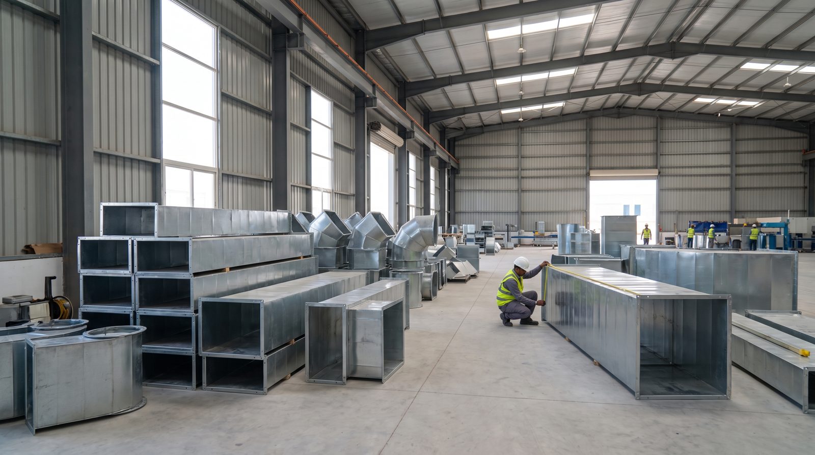
White Arch delivers ductwork fabrication and installation in Saudi Arabia as part of complete air distribution scopes with AHUs, FCUs and ventilation, coordinated in BIM and handed over with test records. The same team handles the chilled-water plant behind the air side, covered on our chiller installation and replacement page, and the power and controls under our electrical and MEP services. Project teams can also see our HVAC contractor in Dammam and HVAC contractor in Riyadh pages, the White Arch solutions for the wider delivery model, and the markets we serve.