VRF vs Chiller for Commercial Buildings: Which System Suits Which Project
Neither system is better in every case. VRF usually suits low and mid-rise commercial buildings with many independently controlled zones and loads up to a few hundred tons, while a chiller plant usually suits large towers, malls, hospitals, data centers and campuses where scale, redundancy, fresh-air treatment and service life dominate. The right answer in the VRF vs chiller which is better question comes from building type, size, plant space, redundancy needs and the part-load profile.
- VRF vs chiller: which is better depends on the building
- Decision matrix by building type and size
- Size and the crossover point
- What is a chilled water system?
- Air cooled vs water cooled chiller
- Primary secondary chilled water system and delta T
- Lifecycle: looking past first cost
- Plant space and building integration
- Redundancy and resilience
- Part-load performance
- Ducted split vs VRF system
- Hybrid systems: using both
- How White Arch supports the decision
VRF vs chiller: which is better depends on the building
VRF vs chiller which is better? Asked in the abstract, the question rarely produces a useful answer, because each system wins on a different kind of building. The practical form of the question, VRF vs chiller plant for this specific project, has to be answered against five criteria: building type and size, lifecycle, plant space, redundancy and part-load behavior. When developers and consultants frame VRF vs chiller which is better this way, the choice usually becomes clear early in concept design, and the rest of this guide works through VRF vs chiller which is better criterion by criterion.
This guide is a decision tool for facility managers, MEP consultants and developers working on commercial and institutional buildings. It deliberately avoids repeating product basics, since our VRF vs VRV guide already covers what a VRF system is and the DX versus chilled-water split, and keeps VRF vs chiller which is better as the decision in focus. Instead, this guide sets out when to choose VRF or a chiller plant, explains what a chilled water system is for readers who need that grounding, covers air cooled vs water cooled chiller choices, primary secondary chilled water system design and delta T, and shows where the crossover sits. All figures are indicative engineering ranges to confirm against current manufacturer data, the ASHRAE handbook and the Saudi Building Code edition specified for the project.
Decision matrix by building type and size
The matrix below reflects common engineering practice on commercial and institutional projects. Load ranges are indicative, not limits, and every example here is commercial or institutional scale.
| Building type | Typical scale | Usual better fit | Deciding reason |
|---|---|---|---|
| Low-rise office or showroom | Up to a few hundred tons | VRF with DOAS | Many zones, varied hours, no plant room needed |
| Mid-scale hotel | Medium | VRF or chilled-water FCUs | Room-by-room control favors VRF, central kitchens and ballrooms push toward chilled water |
| High-rise commercial tower | Large | Chilled water or district cooling | Riser height and piping limits, central plant efficiency, tenant metering |
| Shopping mall | Large | Chilled water | Large common areas, AHUs with fresh air, tenant connections from a central loop |
| Hospital | Large, critical | Chilled water | Fresh air and humidity control, documented N+1 redundancy, long service life |
| Data center | Constant, critical | Chilled water with CRAH, or dedicated precision cooling | Concurrent maintainability and continuous high load |
| Education campus block | Small to medium | VRF with DOAS | Classroom zoning, after-hours use of selected areas |
| University or institutional campus | Very large | Central chilled-water plant | Diversity across buildings and one plant to operate |
| Mixed-use building with phased tenancy | Medium | Hybrid | Chilled water for the core, VRF for independently leased zones |
Size and the crossover point
There is no fixed tonnage at which a chiller plant automatically beats VRF, but the direction is consistent. A single VRF refrigerant system typically tops out at around 40 to 60 HP nominal, so a building with a cooling load of several hundred tons needs many separate systems, each with its own outdoor units, piping network and controls. As that count grows, the operating advantages of VRF (no plant room, modular installation) give way to the burden of maintaining dozens of independent systems.
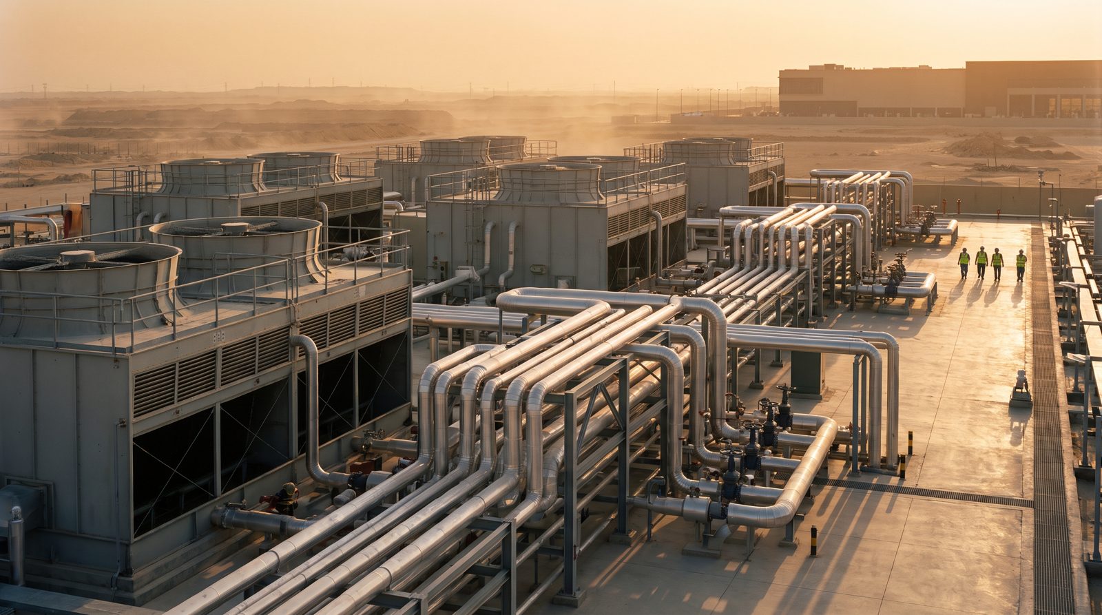
A chiller plant scales the other way. Two or three large chillers with variable speed drives, pumps and cooling towers can serve thousands of tons from one controlled plant, with plant-level efficiency improvements such as condenser water optimization and thermal energy storage. Height is the second scaling factor: refrigerant piping lengths and level differences are capped by the VRF manufacturer, while chilled-water systems handle tall buildings through pressure zoning with heat exchangers, as our MEP contractor in Riyadh page shows for tower risers.
Also read: BTU to Ton Conversion: Sizing Cooling Capacity the Right Way
What is a chilled water system?
What is a chilled water system? A chilled water system cools water in a central chiller, usually to about 6 to 7 °C, and pumps it through insulated pipework to air handling units and fan coil units around the building. At each coil the water absorbs heat from room or ventilation air, warms by a design temperature rise, and returns to the chiller to be cooled again. The chiller rejects that heat either to outdoor air (air-cooled) or to a cooling tower (water-cooled).
| Component | Role in a chilled water system |
|---|---|
| Chiller | Cools the water to the design supply temperature and rejects the heat absorbed |
| Chilled-water pumps | Circulate water from the chiller to the coils and back |
| Air handling units and fan coil units | Pass room or ventilation air over a coil carrying the chilled water |
| Cooling tower (water-cooled only) | Rejects heat from the condenser water loop to the atmosphere by evaporation |
| Expansion tank and controls | Absorb volume changes as water temperature varies and control flow and temperature |
What is a chilled water system good for, in short: central control, the ability to serve many zones from one plant, and the redundancy and lifecycle profile covered later in this guide. Our BTU to ton conversion guide explains how cooling in tons and kW relates to the water flow and temperature rise in such a system.
Air cooled vs water cooled chiller
Air cooled vs water cooled chiller is usually the first chilled-water decision, and it interacts with the VRF vs chiller which is better question because an air-cooled chiller needs the roof space that would otherwise go to VRF outdoor units.
| Factor | Air-cooled chiller | Water-cooled chiller |
|---|---|---|
| Heat rejection | Condenser fans, against outdoor dry-bulb | Cooling tower, against outdoor wet-bulb |
| Efficiency at a given load | Lower, because dry-bulb is higher than wet-bulb | Higher, because wet-bulb is usually several degrees below dry-bulb |
| Water use | None for heat rejection | Make-up water plus treatment for the tower |
| Plant room | None needed for the chiller itself | Chiller room, pumps and water treatment |
| High ambient performance | Capacity and efficiency fall as dry-bulb rises | Tracks wet-bulb, so it holds up better at large loads |
| Typical fit | Small and medium loads, limited water, roof or ground plant | Large loads with long run hours |
Saudi Aramco SAES-A-112 lists a 1% summer design dry-bulb of 44 °C at Riyadh and 45 °C at Dhahran, against design wet-bulb values of 22 °C and 32 °C. The air cooled vs water cooled chiller gap is largest where that dry-bulb to wet-bulb gap is largest, which favors water-cooled plant at Riyadh's dry climate more than at the humid coast, where the wet-bulb itself is high.
Primary secondary chilled water system and delta T
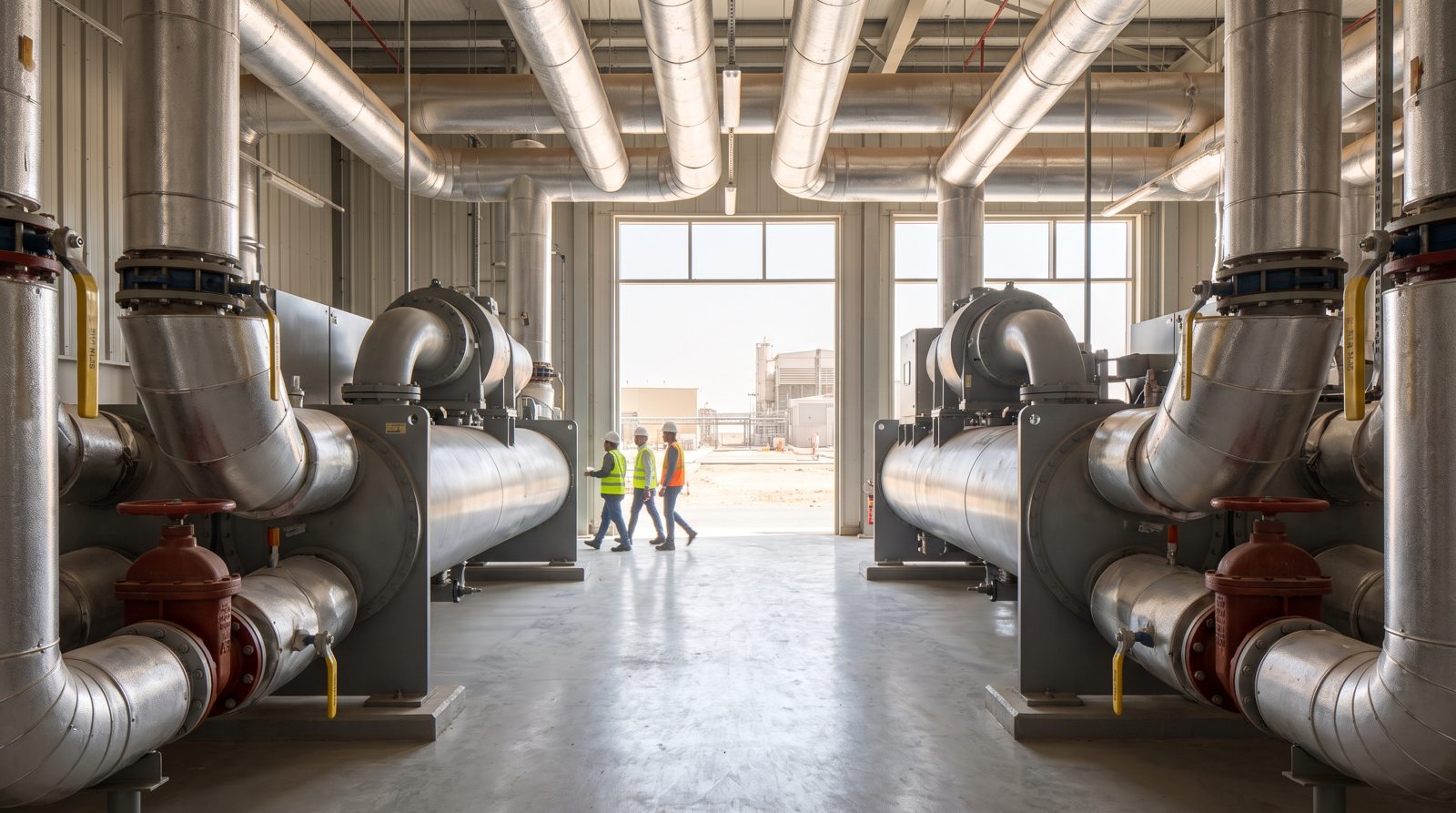
A primary secondary chilled water system is the standard way to protect chillers from the variable flow a building actually needs. The primary loop moves constant flow through each chiller at its design rate, protecting it from flow swings. The secondary loop uses variable speed pumps to vary flow to the building as the load changes. A common pipe, or a bypass, decouples the two loops so a change in one does not force a change in the other. The alternative, variable primary flow, removes the dedicated primary loop and varies flow through the chillers directly, within the limits the manufacturer sets; it saves pumping energy but needs tighter controls. Our chiller upgrades and replacement page covers that conversion as a retrofit measure.
Delta T in a chilled water system is the temperature difference between the water leaving the chiller and the water returning from the coils. A common design value is about 5.5 to 7 K (10 to 12.6 °F), for example 6.7 °C supply and 12.8 °C return. Cooling delivered follows directly from delta T: Q (kW) = flow (L/s) × 4.19 × delta T (K), or in inch-pound units, tons = gpm × delta T (°F) / 24. A system that receives a 10°F delta T design but returns only 6°F in practice needs 10/6, or about 67%, more flow to deliver the same cooling. This low delta T in a chilled water system overloads pumps and chillers that were sized for the design value, so tracking delta T in a chilled water system is one of the simplest health checks an operator can run.
| Design delta T | Actual delta T | Flow needed for the same load |
|---|---|---|
| 10°F (5.6 K) | 10°F (5.6 K) | 100% of design, as intended |
| 10°F (5.6 K) | 8°F (4.4 K) | 125% of design flow |
| 10°F (5.6 K) | 6°F (3.3 K) | 167% of design flow |
Also read: Cooling Load Calculation for Buildings in Saudi Arabia: Design Conditions and Method
Lifecycle: looking past first cost
Lifecycle comparisons should cover service life, replacement events, maintenance effort and energy, not the installed cost alone.
| Lifecycle factor | VRF | Chiller plant |
|---|---|---|
| Typical service life (planning approximation) | Commercial DX equipment is commonly planned at around 15 years | Centrifugal chillers have historically been planned at around 20 to 25 years in ASHRAE service-life data |
| Replacement pattern | Outdoor units and indoor units replaced system by system | Major plant items replaced on a planned schedule, and distribution pipework often outlasts the chillers |
| Maintenance profile | Many distributed units, filters and drain pans in occupied spaces | Concentrated in the plant room and AHU rooms, with water treatment for open condenser circuits |
| Refrigerant exposure | Large refrigerant inventory spread through the building | Refrigerant contained in the chillers inside the plant room |
| Refrigerant transitions | Changes to lower-GWP refrigerants affect every system over time | Affect a small number of chillers, as our chiller upgrades and replacement page explains |
| Efficiency over time | Depends on coil cleanliness and outdoor unit spacing across many units | Depends on water treatment, tube cleaning and plant controls |
The service-life figures above are planning approximations. Confirm them against the current ASHRAE Handbook (HVAC Applications) and manufacturer data before using them in a lifecycle model.
Plant space and building integration
Space often decides the system before efficiency does.
| System | Space it needs |
|---|---|
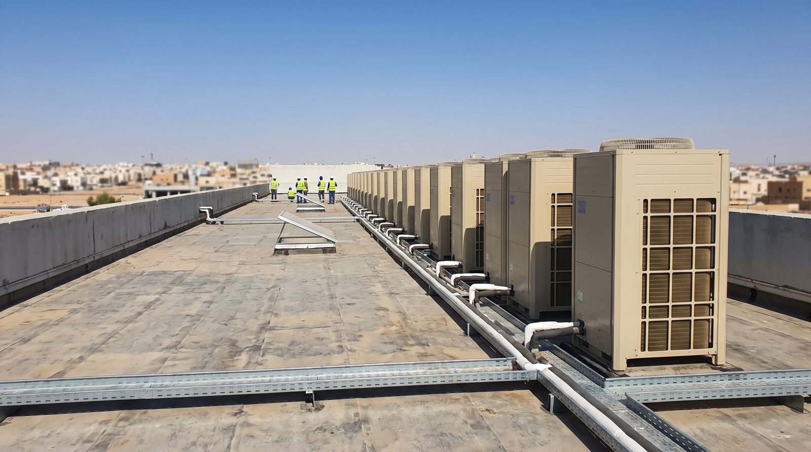
| VRF | Roof or terrace area for outdoor units with manufacturer clearances, refrigerant risers and space for a separate DOAS for ventilation. No central plant room is required. |
| Air-cooled chiller plant | A large, well-ventilated roof or yard area for chillers, plus a pump room and space for chilled-water headers. |
| Water-cooled chiller plant | An internal or basement plant room for chillers and pumps, cooling towers on the roof or at grade, make-up water and water treatment. |
| District cooling connection | An energy transfer station with plate heat exchangers instead of chillers. |
On towers and mixed-use developments, the roof is often contested by facade access, solar, lifts and amenity space. In those cases, a chiller plant with a compact cooling tower footprint, or a district cooling connection, can free more usable roof area than a field of VRF outdoor units.
Redundancy and resilience
Redundancy separates VRF and chiller plants more sharply than any other factor.
| System | How redundancy works |
|---|---|
| VRF | Each refrigerant system serves its own zones. Multi-module outdoor combinations can offer partial backup operation if one module fails, but a refrigerant leak or controller fault takes down that whole system. Redundancy is achieved by overlapping systems, which is rarely practical. |
| Chiller plant | Redundancy is designed in at plant level, typically N+1 chillers, standby pumps, and, for critical facilities, dual feeds and concurrently maintainable piping. Maintenance on one chiller does not interrupt cooling. |
For hospitals, data centers and other critical facilities, that plant-level redundancy is usually decisive in favor of chilled water, as our hospital HVAC page and data center MEP page both show.
Part-load performance
Most commercial buildings spend most operating hours at part load, so part-load efficiency matters more than full-load ratings.
| System | Part-load behavior |
|---|---|
| VRF | Inverter compressors modulate smoothly, and efficiency at partial load is strong, especially in shoulder seasons and outside peak occupancy. |
| Chiller plant | Variable speed drives on chillers, pumps and tower fans, plus staging of multiple chillers, keep each machine near its efficient operating point. Chiller part-load performance is compared using the AHRI 550/590 IPLV or NPLV metrics. |
Long, hot summers mean high loads for many hours, and in that regime a well-controlled water-cooled plant is typically more efficient than air-cooled VRF at peak. In winter and at night, VRF's fine-grained modulation can be the better performer for lightly loaded zones. An hourly energy model, not a single rating, is the reliable way to compare the two for a specific building.
Also read: Signs Your Chiller Needs Replacing: Repair, Retrofit or Replace
Ducted split vs VRF system
For the smaller end of the commercial range, the comparison is often VRF against ducted split units rather than against chillers. A ducted split serves one zone per outdoor unit with a single compressor circuit, which is simple and robust for a single showroom or an isolated hall. A VRF system serves many indoor units from one modular outdoor system, with individual control and central monitoring. In the ducted split vs VRF system comparison, where a floor has more than a handful of zones with different schedules, VRF usually wins; for one large open zone, a ducted split or a packaged unit can be the cleaner solution. The number and diversity of zones decides the ducted split vs VRF system question just as it decides VRF vs chiller which is better at larger scale, and a consultant should document that zone count before the ducted split vs VRF system choice is finalized.
Hybrid systems: using both
Many projects combine the two. A typical pattern is a central chiller plant for the building core, AHUs and common areas, with VRF serving zones that operate on different hours, such as a security control room, a retail unit with late trading or a server room with a dedicated system. Hybrid designs need clear interface definitions between the mechanical, electrical and controls scopes, which is where one accountable contractor reduces coordination risk. Our HVAC retrofit page covers phasing a hybrid upgrade around an occupied building.

How White Arch supports the decision
We design, install and commission both chilled-water plants and VRF/VRV systems on commercial and institutional projects across the Kingdom, mobilizing from Dammam. Because we deliver both, the recommendation follows the building rather than a preferred product. Details of the scope are on our HVAC services page, with sector experience on our markets page and integrated delivery on our solutions page.