
CRAC vs CRAH and the Rest: Data Center Cooling Architectures Compared
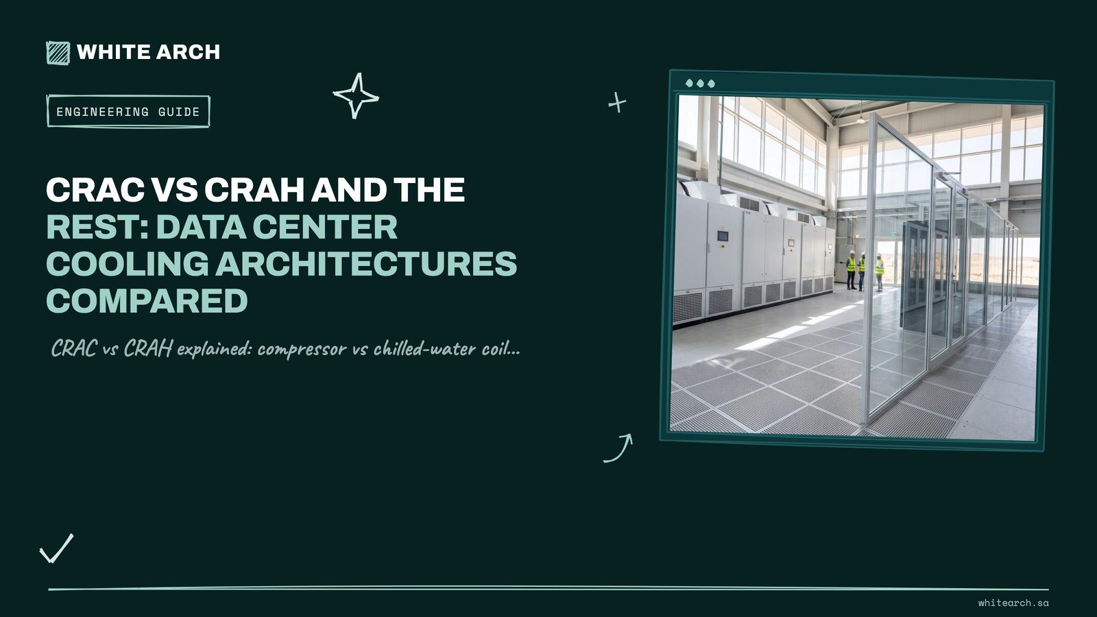
A CRAC (computer room air conditioner) is a self-contained unit with its own compressor and refrigerant circuit that rejects heat to a condenser. A CRAH (computer room air handler) has no compressor: it uses fans and a chilled-water coil supplied by a central chiller plant. In the CRAC vs CRAH choice, CRAC units suit smaller rooms and sites without chilled water, and CRAH units suit larger facilities where a chiller plant gives better efficiency and easier scaling.
- CRAC vs CRAH: the core difference
- How a CRAC unit works
- How a CRAH unit works
- CRAC vs CRAH comparison table
- Other data center cooling types
- Hot aisle cold aisle containment
- Free cooling limits in the Saudi climate
- N+1 redundancy cooling
- Data center humidity control
- Data center design standards to reference
- How to choose between CRAC, CRAH and the alternatives
CRAC vs CRAH: the core difference
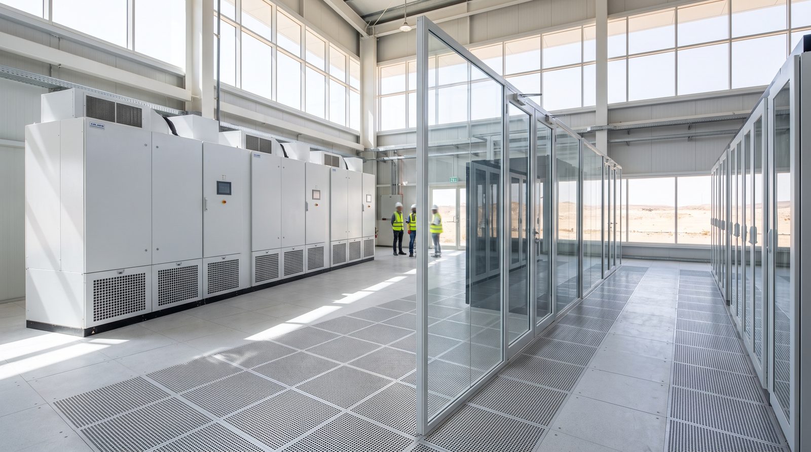
The CRAC vs CRAH question comes down to where the refrigeration happens. In a CRAC, the vapor compression cycle (compressor, evaporator coil, expansion device) sits inside the unit on the data hall floor, and heat leaves through a remote air-cooled condenser or a water or glycol loop. In a CRAH, the unit on the floor is only an air handler: fans move air across a chilled-water coil, a valve modulates the water flow, and the compressors live in the chiller plant. Every other point of comparison in CRAC vs CRAH, from efficiency to redundancy to maintenance, follows from that one design difference.
For owners and consultants, CRAC vs CRAH is rarely a pure equipment choice. It is a choice about the whole cooling architecture: whether the site will have a chiller plant, how heat will be rejected in summers of 44 to 45 °C (Saudi Aramco SAES-A-112 lists those design dry-bulb values for Riyadh and Dhahran), how the system will be made concurrently maintainable through N+1 redundancy cooling, which data center design standards govern it, and how it will grow as rack densities rise. This guide sets out CRAC vs CRAH in detail, then places both among the other data center cooling types now being specified, including in-row, rear-door and direct-to-chip liquid cooling. We install these systems through our data center MEP service, so the CRAC vs CRAH trade-offs below come from site work as well as theory.
How a CRAC unit works
A CRAC unit is a packaged precision air conditioner built for the high sensible heat ratio of IT load, where almost all of the heat is sensible and very little moisture needs to be removed. Warm return air from the hot aisle or ceiling plenum passes over the unit's evaporator coil, and the refrigerant absorbs the heat. The compressor raises the refrigerant pressure and temperature, and the heat is rejected through one of three common arrangements.
| Arrangement | How heat is rejected | Note |
|---|---|---|
| Air-cooled | Refrigerant piping runs to a remote condenser on the roof or at grade | Pipe length and height limits apply |
| Water-cooled | A condenser inside the unit rejects heat to a condenser water loop and cooling tower | Adds a tower and water treatment |
| Glycol-cooled | A glycol loop carries heat to a dry cooler | An economizer coil can allow partial free cooling in cool weather |
Modern CRAC units use variable-speed compressors and EC fans to follow the load, and some include pumped-refrigerant economizers. The strengths are independence (each unit is its own cooling system, so there is no central plant to fail) and suitability for small and medium rooms, edge sites and retrofit spaces without chilled water. The limits are efficiency at scale, refrigerant pipe length to remote condensers, and the fact that every unit adds a compressor to maintain inside or near the white space.
How a CRAH unit works
A CRAH unit contains fans, filters, a chilled-water coil, a control valve and controls. The cooling capacity depends on chilled-water flow, entering water temperature and airflow. Because there is no compressor in the unit, a CRAH is mechanically simpler on the data hall floor, and capacity is set centrally by the chiller plant, which can use large high-efficiency centrifugal or screw chillers and, where the climate allows, water-side economizers.
CRAH units pair well with elevated chilled-water temperatures. When the hall runs inside the ASHRAE recommended range with good containment, supply water can be several degrees warmer than traditional comfort-cooling values. That raises chiller efficiency, reduces unwanted dehumidification at the coil, simplifies data center humidity control and widens the hours in which free cooling contributes. The trade-off is dependence on the chiller plant and the piping network, so chillers, pumps, valves and pipe sections all need redundancy and isolation to keep the whole system concurrently maintainable. Chiller capacity follows the heat load directly: 1 MW of IT load is about 284 tons of refrigeration, as our BTU to ton conversion guide explains.
CRAC vs CRAH comparison table
| Factor | CRAC (computer room air conditioner) | CRAH (computer room air handler) |
|---|---|---|
| Cooling source | Own DX refrigerant circuit | Chilled water from a central plant |
| Compressor | In the unit | None in the unit (in the chillers) |
| Heat rejection | Remote condenser, condenser water or glycol dry cooler | Chiller plant with cooling towers, air-cooled chillers or dry coolers |
| Typical fit | Small to medium rooms, edge sites, buildings without chilled water | Medium to large and hyperscale facilities |
| Efficiency at scale | Lower, with many small compressors | Higher, with large chillers and economizer options |
| Scaling | Add units and condensers | Add units on existing loops if plant and piping capacity allow |
| Redundancy model | N+1 units, each independent | N+1 units plus redundant chillers, pumps and piping paths |
| Maintenance in the white space | Compressors and refrigerant work near IT | Fans, filters, valves and coils only |
| Leak consideration | Refrigerant | Water in or near the hall, so leak detection and drip trays are needed |
The CRAC vs CRAH comparison also shows why most large facilities choose chilled water: the compressors move to a plant that can be run, maintained and expanded away from the IT equipment. It is also the base for N+1 redundancy cooling, and for most other data center cooling types.
Also read: Cooling Load Calculation for Buildings in Saudi Arabia: Design Conditions and Method
Other data center cooling types
Room-level CRAC and CRAH units are only two of the data center cooling types now in use. Higher densities have pushed cooling closer to the heat source.
| Cooling type | How it works | Where it fits |
|---|---|---|
| Fan walls and air handling units | Large chilled-water or evaporative air handlers outside the hall push air through a wall into the room | Hyperscale halls with slab floors and hot aisle containment |
| In-row cooling | Chilled-water or DX units placed between racks draw from the hot aisle and supply the cold aisle | Medium to high density rows and retrofits |
| Rear-door heat exchangers | A chilled-water coil replaces the rack rear door, either passive (rack fans only) or active (door fans) | High-density racks in an existing room |
| Direct-to-chip liquid cooling | Cold plates on processors connect through a coolant distribution unit (CDU) to the facility water loop | AI and high-performance computing racks |
| Immersion cooling | Servers are submerged in a dielectric fluid, single-phase or two-phase | Specialized high-density deployments |
Most new facilities designed for AI loads are hybrids, and hot aisle cold aisle containment still applies to their air side, with N+1 redundancy cooling on the shared plant. Air cooling (CRAH or fan walls) still handles memory, storage, network gear and the residual heat that liquid systems do not capture, while direct-to-chip loops take the processor heat. ASHRAE's fifth edition also defines a high-density class, H1, with a recommended inlet range of 18 to 22 °C and an allowable range of 15 to 25 °C, narrower than the standard 18 to 27 °C. Both air and liquid systems draw on the same chilled-water or facility-water plant, which is why piping should be designed with valved tap-off points for future CDUs. Our data center cooling types sit on a plant described on our chiller installation page.
Hot aisle cold aisle containment
Hot aisle cold aisle containment is the single most effective improvement to any air-cooled room, whether it uses CRAC or CRAH units, and it works with every one of the data center cooling types that moves air through a hall. Racks face front to front so cold air is supplied to a shared cold aisle, and exhaust is collected from a shared hot aisle. Containment physically separates the two with doors, roof panels or chimney ducts.
Hot aisle cold aisle containment comes in two forms, with supporting measures that both need.
| Approach | What it does | Notes |
|---|---|---|
| Cold aisle containment (CAC) | Encloses the cold aisle, and the rest of the room becomes the hot return | Simple to retrofit on raised floors |
| Hot aisle containment (HAC) | Encloses the hot aisle and ducts exhaust to the units or a ceiling plenum | The room stays at supply temperature, which is more comfortable for staff |
| Supporting measures | Blanking panels, sealed cable cutouts, correct perforated tile placement and sealed gaps under racks | Needed with either approach |
Containment stops bypass air (cold air returning without passing through IT) and recirculation (hot exhaust reaching rack inlets). With both controlled, units can operate at higher return temperatures and lower fan speeds, and supply temperatures can move up toward the top of the recommended range, which also eases data center humidity control. Hot aisle cold aisle containment therefore pays back in efficiency as well as stability. Efficiency across the industry has changed little: Uptime Institute's 2024 survey found average annual PUE of 1.56 at respondents' largest data centers, and it noted that average PUE had stayed mostly flat for the fifth consecutive year (Uptime Institute 2024 survey; Uptime Institute survey data via Statista). PUE is total facility energy divided by IT energy, so containment and warmer supply temperatures are among the few levers that move it.

Also read: BTU to Ton Conversion: Sizing Cooling Capacity the Right Way
Free cooling limits in the Saudi climate
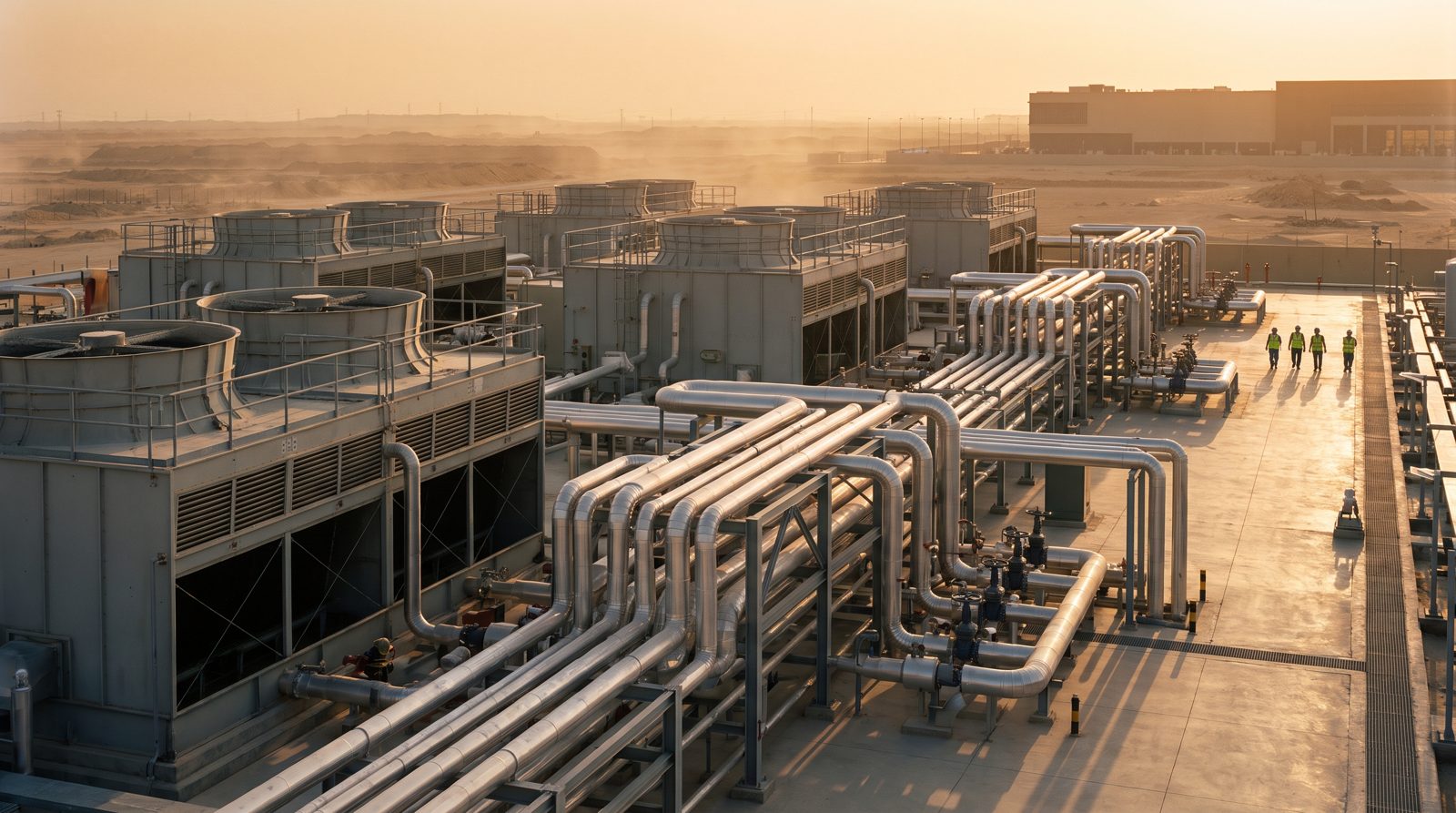
Free cooling, or economization, uses outdoor conditions to reject heat without running compressors. Its value depends entirely on climate. Riyadh and the central region are hot and dry, with summer peaks of 44 °C or more and frequent dust, while Dammam, Jubail and Jeddah combine high temperatures with high humidity. Direct air-side economizers face both dust loading and limited suitable hours. Water-side economizers, which place a heat exchanger between the cooling tower or dry cooler loop and the chilled-water loop, are more practical, but in these conditions they mainly contribute in winter months and at night, and mostly as partial free cooling.
Raising the chilled-water supply temperature is what extends those hours, and N+1 redundancy cooling applies to the heat rejection too, so every tower or dry cooler needs a spare. Data center humidity control also shapes economizer hours, because outdoor air must be dried before it enters the hall. Evaporative approaches can be effective inland, but water consumption must be weighed carefully where make-up water is desalinated. ASHRAE Standard 90.4, the energy standard for data centers, is the usual reference for evaluating these trade-offs, and our cooling load calculation guide sets out the design conditions.
N+1 redundancy cooling
N+1 redundancy cooling means installing one more unit than the number (N) needed to carry the design IT load, so any single unit can fail or be maintained without loss of cooling. The data center design standards define the principle, and for a credible N+1 redundancy cooling design, the redundancy must carry through the whole cooling path.
| Layer | What N+1 means | Why it matters |
|---|---|---|
| Terminal units | N+1 CRAC, CRAH, in-row or fan wall units per hall or zone, not just across the whole building | A failure in one hall cannot be covered by a unit in another |
| Plant | N+1 chillers, pumps and heat rejection, with valving so each can be isolated | Any machine can be maintained while the load is carried |
| Distribution | Looped or dual-path chilled-water piping, and for Uptime Tier III, concurrently maintainable distribution paths | A valve or pipe section can be taken out of service |
| Power and controls | Units fed from alternate sources and controls that do not create a single point of failure | Cooling must survive the same failures the IT load does |
The table below counts equipment for an illustrative 1 MW IT hall, using 50 kW room units and 150 TR chillers. N means the units needed for the load, and N+1 adds one.
| Item | N | N+1 | Note |
|---|---|---|---|
| Room units at 50 kW each | 20 | 21 | 1,000 kW divided by 50 kW |
| Compressors in a CRAC design | 20 | 21 | One compressor circuit per unit, plus condensers |
| Chillers at 150 TR each in a CRAH design | 2 (300 TR) | 3 (450 TR) | 1 MW is about 284 TR |
A useful operating practice is to run all units, including the redundant one, at reduced fan speed instead of leaving one switched off. Because fan power falls roughly with the cube of speed, five units at 80% airflow use, in ideal affinity-law terms, about a third less fan power than four units at full speed (5 × 0.8³ = 2.56 against 4), and the hall has no cold start on a failure. Real savings are lower because of fixed losses, but the principle holds. The redundant plant is where hot tapping and pipe freezing earn their place, because they let a valve or branch change without removing the redundancy, as our guide to pipe freezing vs draining the system explains.
Also read: Pipe Freezing vs Draining the System: Which Isolation Method Costs You Less Downtime
Data center humidity control
Data center humidity control has become less restrictive as research has refined the envelope, and ASHRAE TC 9.9 is the first of the data center design standards to consult. The ASHRAE TC 9.9 thermal guidelines, fifth edition, recommend a server inlet temperature of 18 to 27 °C for the common equipment classes, with humidity expressed mainly by dew point: a lower limit of minus 9 °C dew point and an upper limit of 15 °C dew point, plus a relative humidity ceiling of 70% where gaseous contamination is low and 50% where it is high (ASHRAE TC 9.9 reference card, fifth edition). The previous ceiling was 60%. Allowable ranges widen by class, and the table lists them.
| ASHRAE class | Allowable inlet temperature | Typical use |
|---|---|---|
| Recommended (A1 to A4) | 18 to 27 °C | Normal operating target |
| A1 | 15 to 32 °C | Enterprise data centers with tight control |
| A2 | 10 to 35 °C | Less tightly controlled spaces |
| A3 | 5 to 40 °C | Wider environmental tolerance |
| A4 | 5 to 45 °C | Widest tolerance, for specially rated equipment |
Confirm the values against the current edition and the IT manufacturer's warranty conditions. Data center humidity control has four practical issues in Saudi facilities.
| Issue | What happens | What to do |
|---|---|---|
| Coastal outdoor air | Make-up air in Dammam, Jubail or Jeddah carries a heavy latent load | Dry it in a dedicated outdoor air unit before it enters the hall, so CRAH coils can run dry at elevated water temperatures |
| Dry inland conditions | Riyadh air can fall well below the lower dew point limit in winter | Centralize any humidification and control it on dew point |
| Units fighting each other | Individual units humidify and dehumidify at the same time | Control humidity centrally with a common setpoint and deadband |
| Sealing | Leaks let outdoor moisture into the hall | A well-sealed room with controlled make-up air makes humidity far easier to hold than any equipment setting |
Data center design standards to reference
Specifications usually name one topology standard and several engineering references. The main data center design standards are in the table. Tier III expects N+1 redundancy cooling with concurrently maintainable paths, and Uptime Institute, which publishes the Tier Standard, has offices in Dubai and Riyadh (Uptime Institute 2024 survey).
| Standard | What it covers |
|---|---|
| Uptime Institute Tier Standard: Topology | Tier I to IV, where Tier III is concurrently maintainable and Tier IV is fault tolerant |
| ANSI/TIA-942 | Telecommunications infrastructure standard for data centers, Rated-1 to Rated-4 |
| EN 50600 | European series covering facilities and infrastructure, with availability classes 1 to 4 |
| ASHRAE TC 9.9 thermal guidelines | Recommended and allowable temperature and humidity at IT inlets |
| ASHRAE Standard 90.4 | Energy standard for data centers |
These data center design standards are not interchangeable, and Uptime Tier certification is issued only by the Uptime Institute, so the employer's requirements should state which scheme governs. Our data center MEP page explains what the Tier 3 requirements mean for installation, and guidance on thermal envelopes and energy standards is on ashrae.org. Feeder and busway design for the same facilities follows the method in our voltage drop calculation guide.
Also read: Signs Your Chiller Needs Replacing: Repair, Retrofit or Replace
How to choose between CRAC, CRAH and the alternatives
Among the data center cooling types, choose CRAC units when the room is small or isolated, no chilled water exists or is planned, and independence of each unit is valued. Choose CRAH units, or fan walls, when the facility is large enough to justify a chiller plant and efficiency over the life of the building matters. Plan for close-coupled or liquid cooling where rack densities exceed what room-level air can handle, and make sure the chilled-water plant and piping have capacity and valved connection points for that future. Whatever the choice, specify hot aisle cold aisle containment, N+1 redundancy cooling, data center humidity control and the data center design standards in the employer's requirements.
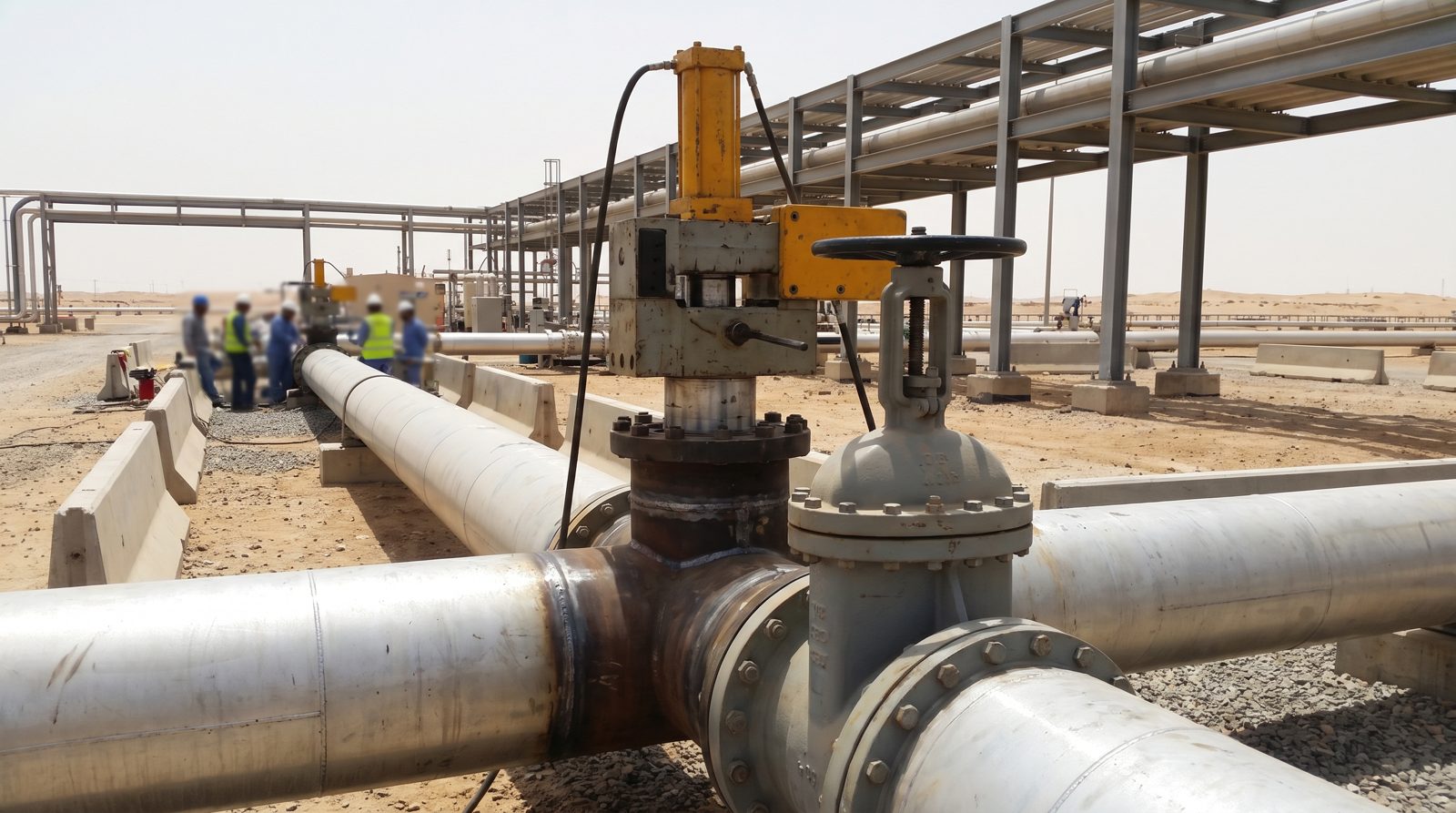
We install and commission chilled-water plant, CRAH and in-row units, containment interfaces and the power distribution that feeds them, and we use hot tapping and pipe freezing to connect new cooling to live chilled-water systems without draining loops that serve operating halls. Details are on our HVAC services page, our solutions page and our markets page, with regional delivery from our HVAC contractor in Riyadh and HVAC contractor in Dammam teams. For plant upgrades around a live facility, see our HVAC retrofit page.